Alex Nguyen

Build instructions

Alex Nguyen

I design, prototype, build and launch. Mechanical engineering at the University of Toronto; mechatronics co-op on the computer-vision team at Martinrea.

Parts
10
Designer
Alex
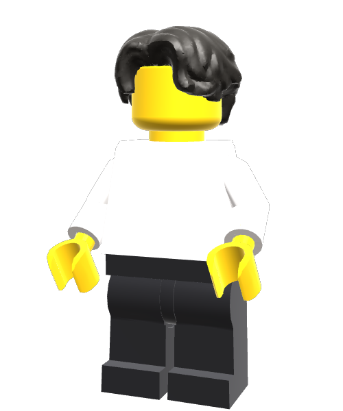
Alex's 3D-printed figure, assembled: black hair, yellow head and hands, white torso and arms, black legs.

On the box: a LEGO-style minifigure I designed part by part in CAD and 3D-printed. Scroll and it comes apart into its printed parts.

Step 1: UofT Supermileage

Legs and hips go first: everything else stands on them. Since September 2023 I’ve helped build three hydrogen cars, and I now lead the aero-structural team.

  • 1×hips
  • 2×legs

In this chapter: Mist Rider, Momentum and Velocity, our three hydrogen cars.

Read the chapter

4

Chapter 1 · Legs and hips

UofT Supermileage

Aero-structural Lead · September 2023 – Present

Three hydrogen cars for the Shell Eco-marathon. Each block is one car, in the order we built them, and the third one races you to the flag.

5

Velocity, hydrogen car V3

Aero-structural Lead for the 2026 Shell Eco-marathon car

Earlier cars were hard to manufacture, iterate and scale, and thin simulation meant repeated mistakes. For the third generation I designed an integrated monocoque chassis that is also the aerodynamic shell.

  • 7 complete design iterations, each run through ANSYS CFD for flow, pressure and drag.
  • FEA on competition load cases cut the material candidates from four to one.
  • DFMA to simplify geometry and part count, so a student team could build it.
  • 0.22drag coefficient (Cd)
  • −38%drag vs. last year’s car
  • 7design iterations
  • 4→1materials after FEA

6

Velocity, finished
The seven design iterations
CFD pressure contour

7

From CAD to carbon fibre in 4 months

Leading 20+ people through design, analysis and manufacturing

Build sequence

  1. Positive moldsliced the CAD, CNC-machined the sections, joined and fibreglassed them
  2. Negative moldrelease agents, vacuum-bagged fibreglass layups, post-processing
  3. Carbon-fibre shelllaid up in the negative mold, post-processed, then painted
  4. Inspectionpassed, then raced at the Indianapolis Motor Speedway
  • 20+engineers led
  • 4months, concept to raced car

8

CNC-machining the positive mold
Vacuum-bagged layup
Carbon-fibre shell in progress
Passed technical inspection
Division leads at Indianapolis
Part of my team
Velocity, the finished shell

9

Momentum, V2

Shell Eco-marathon 2025

The first car failed technical inspection, so V2 was a redesign with a real method behind it: better structure, packaging and system integration. I designed the door and hinge system, integrated into the body shell with off-the-shelf hardware, and helped build the carbon-fibre shell from composite molds.

  • −90%hinge cost, same function
Momentum
On track, 2025
Hinge system CAD
Door built into the shell

10

Mist Rider, V1

The first car, from scratch

No reference design, no process: every design, manufacturing and assembly method had to be learned. I designed the door hinge and did hands-on aero-body work, sanding to the contours and laying up composites.

It failed technical inspection. Those lessons shaped V2 and V3, and they are why the third car passed.

Mist Rider, finished
Building the aero body
Door hinge CAD

11

Step 2: Martinrea

The torso is the core of the build, like this co-op. Since May 2026 I’ve been a mechatronics engineering intern on Martinrea’s computer-vision team, building the hardware inspection depends on.

  • 1×torso

In this chapter: the inspection system, a lens lock, an end effector and lighting control.

Read the chapter

12

Modular inspection system

Martinrea, May 2026 – Present

I architected and deployed a process-quality inspection system for 500+ automotive parts, end to end: mechanical design and CAD, hardware selection, the inspection flow and the computer vision. YOLO models check each part’s welds, slots and holes, and confirm the part is actually in the fixture and in the right orientation; the operator screen keeps a live good/bad count.

I presented it to key stakeholders and secured 20+ follow-on deployment projects across manufacturing plants.

  • 500+parts covered by one system
  • 20+follow-on deployments

14

Inspection flow

  1. Part loadedon the hole-pattern table
  2. Image capturecamera, locked lens
  3. YOLO modelpresence, orientation, welds, slots, holes
  4. Validationgood or bad
  5. Operator screenlive counts
Inspection table CAD
Operator screen: every feature checked

Watch it run on the plant floor (YouTube, 33 s) (opens in a new tab)

15

C-mount lens lock

Martinrea, 2026. Now on 400+ cameras

Vibration from nearby presses, or a stray hand, knocks a lens’s focus and aperture rings out of position. Long exposure to vibration can even unscrew the lens off the camera.

How it goes together

  1. Split ring gearsclamp onto the focus and aperture rings
  2. Sliding outer gearlocks both rings at once
  3. Captive bolts and a stopperkeep the slider in place and the lens from untwisting

It’s a parametric SolidWorks model: one global variable, the lens diameter, fits a new lens. I wrote the print and assembly guide too.

16

  • 400+cameras fitted
  • 1variable to fit a new lens
Lens lock on a camera
Exploded CAD
Stopper removed

17

Hybrid end effector and a damping fixture

Martinrea, 2026. Confidential, so no photos

A robotic test bench has to handle everything from large steel parts to small, irregular objects, and one gripper can’t do both. I designed a fully 3D-printed end effector that combines a magnet for large steel parts, a gripper for small ones, and a camera on the tool for vision-based sorting.

The magnet is safe here because it works inside a guarded robot cell, unlike the operator-loaded inspection table.

The companion piece is a robot-compatible locating and damping fixture for long fluid-line assemblies. It steadies the part without getting in the robot’s way.

18

Where the end effector stands

  1. DoneDesign and 3D printmagnet, gripper, camera
  2. In progressBench testingpick-and-place motion
  3. NextVision sortingwith the tool’s own camera

Why the fixture matters

  1. Part damped
  2. Longer exposure
  3. Higher f-stop
  4. Greater depth of field
  5. Better vision data
  • 3tools in one: magnet, gripper, camera

19

Lighting control hardware

Martinrea, 2026

Industrial 24 V vision lights dim on a 0–10 V signal, usually from a PLC or a dial. The goal: control brightness and strobing straight from Python.

Iteration 1

Microcontroller PWM through an optocoupler for isolation, a low-pass filter, then op-amps to scale it to 0–10 V. Relays switch between strobing on the camera trigger and continuous light.

Iteration 2

An I²C multiplexer, 12-bit DACs and gain-of-2 op-amps, so one microcontroller dims up to 8 lights individually. Breadboard-tested, and being added to our existing lighting PCB as a new feature.

A separate project

CEO vehicle light fixture

A scissor-lift mount that holds a light on the CEO’s vehicle, taken from SolidWorks CAD through 3D-printed prototypes to a machined assembly, with no permanent change to the vehicle. The light itself is patented, so it isn’t shown.

20

Iteration 1 signal path

  1. Python
  2. MCU PWM
  3. Optocoupler
  4. Low-pass filter
  5. Op-amp
  6. 0–10 V
  • 8lights per microcontroller
  • 2iterations, breadboard-tested
KiCad schematic
Block diagram

21

Step 3: Neuro-Echo

The head goes on the torso, and so does Neuro-Echo: a wearable you put on your head that reads text aloud. It took 1st place at UTEK 2026.

  • 1×head

In this chapter: the problem, the build and the result.

Read the chapter

22

Chapter 3 · Head

Neuro-Echo

UTEK Senior Design Competition · January 2026

A low-cost, hands-free wearable that reads signs aloud for people with any level of visual impairment.

23

Neuro-Echo

UTEK Senior Design Competition, January 2026. 1st place

People with any level of visual impairment have trouble reading signs from a distance. Our goal was to make sure they still know what a sign says.

We built a low-cost, hands-free wearable that turns visual text into real-time audio: an ESP32-CAM captures the image, an Arduino Uno handles control, OCR-based recognition drives speech output, and an LCD supports partial vision.

  • 1stplace at UTEK 2026

24

Prototype, worn
The hardware
LCD output
Award ceremony

25

Step 4: A 3-DOF robotic arm

Arms next, for the next hackathon, the same month: at the Ontario Engineering Competition I designed and built a three-axis arm with cycloidal-drive joints.

  • 2×arms

In this chapter: the arm and its seven competition tasks.

Read the chapter

26

Chapter 4 · Arms

3-DOF robotic arm

Ontario Engineering Competition · January 2026

The next hackathon, the same month: a three-axis arm with cycloidal-drive joints, built and run at the competition. Seven tasks, one block each.

27

3-DOF robotic arm

Ontario Engineering Competition, January 2026

  • A detailed SolidWorks model of the whole arm: mechanical layout and joint architecture.
  • Cycloidal-drive joints for more torque capacity, less backlash and precise motion.
  • A working prototype with Arduino-based motor control.

There are no photos of this one, so the arms on the figure will have to stand in.

28

Competition tasks

  1. Task 1: completed
  2. Task 2: completed
  3. Task 3: completed
  4. Task 4: completed
  5. Task 5: completed
  6. Task 6: not completed
  7. Task 7: not completed

5 of 7 completed (70%), placing among the top-performing teams.

  • 70%of competition tasks
  • 3cycloidal-drive joints

29

Step 5: Hands-on projects

Hands next, for the things I built in design courses: a CNC router held to a budget and a humidifier hidden in a shelf.

  • 2×hands

In this chapter: a CNC router and a guitar humidifier.

Read the chapter

30

Chapter 5 · Hands

Hands-on projects

Mechanical and engineering design course projects

A machine built to a budget, and a product built for a client.

31

Hobbyist CNC router

Mechanical design final project, 2024

A beginner-friendly router that balances affordability, reliability, precision and customizability within a $2,500 budget.

  • Timing-belt and lead-screw motion in a small hobbyist footprint.
  • Interchangeable parts, a transparent safety guard, a vacuum spindle mount and a vacuum workholding board.
  • Structure validated at 73× the intended load by FEA.
  • 73×load margin by FEA
  • $2,500total budget

32

SolidWorks render
Engineering drawing
FEA: T-slot beam
FEA: gantry bracket

33

Solid-wood guitar humidifier

Engineering design final project

Solid-wood guitars are very sensitive to humidity swings. The client wanted stable humidity without frequent maintenance, at low cost and out of sight.

I evaluated 100+ solutions in SolidWorks and built a waterline-fed, autonomous humidification system hidden in a wall-mounted shelf. The working prototype, tested under real conditions, holds ASHRAE comfort ranges.

  • 43–55%relative humidity held
  • $300budget per guitar
  • 100+solutions evaluated

34

Working prototype
Prototype running
Control electronics
Nozzle CAD

35

Step 6: CAD for fun

The finishing touch is the personal one. Outside work and school I design and print things for my desk, my PC and as gifts, including this figure.

  • 1×hair piece

In this chapter: eight hobby prints, and the story of this figure.

Read the chapter

36

Chapter 6 · Hair

CAD for fun

Hobby prints · designed and printed by me

If I want something, I model it and print it, including this figure. Watch it come apart on the print bed.

37

CAD for fun

Hobby prints, designed and printed at home

If I want something, I model it, print it and refine it. Some designs are practical; some are just for fun.

  • An air duct with a fan connection that routes my 3D printer’s exhaust straight into my air purifier.
  • A microphone stand that mounts to my monitor, pegboard mounts for my most-used tools, and filament racks.
  • A custom front cover for my Lian Li A3 PC case, a Polaroid photo book, decor and gifts.
  • And the figure on this page: ten parts, all modelled in CAD and 3D-printed.

38

Printer-to-purifier duct
Monitor mic stand
Gifts
Lian Li A3 front cover
Pegboard tool mounts
Filament racks
Polaroid book
PC decor

39

Finished model

Ten printed parts, added one chapter at a time. The instruction drawings give way to the real thing: the same CAD I printed, turning once on the turntable as you scroll.

  • 10parts
  • 6steps
The finished figure, front view.

40

Tools used in this build

CAD and design

  • SolidWorks (CSWA)
  • Fusion 360
  • Onshape
  • AutoCAD
  • GD&T
  • DFM/A

Simulation

  • ANSYS
  • FEA
  • CFD

Vision and software

  • Python
  • OpenCV
  • YOLO model training
  • MATLAB
  • C/C++
  • Git
  • Linux

Electronics

  • Arduino
  • Raspberry Pi
  • KiCad
  • LTspice
  • Soldering

Manufacturing

  • 3D printing
  • CNC machining
  • Composite layups
  • Lathe, mill, drill press
  • Rapid prototyping

41

Education

University of Toronto
BASc Mechanical Engineering + PEY Co-op
Minor in Robotics & Engineering Business
Sep 2023 – 2028

The builder, off duty

42

Ready for the next build

I’m looking for robotics, mechatronics and hardware design work. Send me the problem.

© 2026 Alex Nguyen. The figure is rendered live from my own CAD with a small WebGL renderer.